Digital Circuit Design
TEAM MEMBERS
ABSTRACT
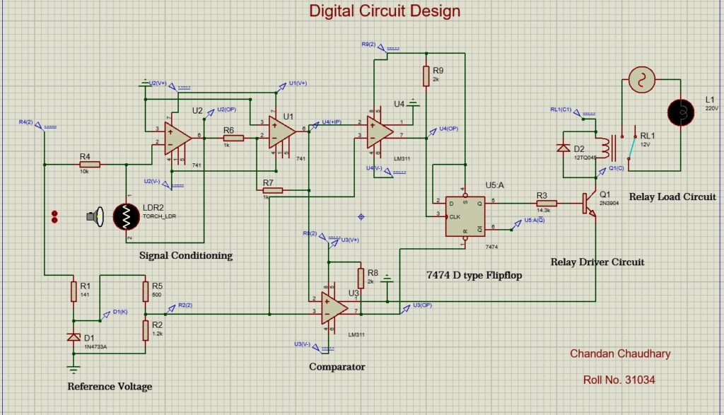
The on/off design here is the modification of the analog on/off control system design with the integration of digital logic components like flipflop and comparator. The LDR sensor used is integrated with operational amplifier to get the signal values. The output from the signal conditioning of the LDR sensor is then fed to the comparator (say Comparator A) to get either high value or a low value. Similarly, the reference voltage is also fed into the other comparator (say comparator B). The output of the signal conditioning is fed in the comparator B where the reference voltage is set. The output from the comparator B is now fed to digital component of the design which is the D type flipflop (IC 7474). The flip flop is used to store the result. The output from the comparator A (from the sensor) is fed to the clock of the flip flop while the output of the comparator B (reference voltage) is fed to the reset pin of the flipflop. The high signal from the comparator B clears and resets the flip flop and prepares it for new signal. The D input and the set of the flip flop is triggered high. The Q output of the flipflop is connected to the relay driver circuit thus to drive the relay.
The flip flop is a digital circuit component which means the IC works on digital signals either high or low. I use comparator in the analog output of the signal conditioning from the sensor to change the analog signal to digital in form of high and low. The reference voltage is also input from the comparator as in form of digital values of high or low. The flipflop works on receiving the digital signal gives the output Q and Q’.
The output of the flipflop is used in the relay driver circuit to trigger the relay and thus to run the load or appliances as required.