Relay-Based Automatic Voltage Stabilizer
Project Team
Overview
This project designed, fabricated, and characterized an automatic voltage stabilizer for residential use in regions with high grid voltage variability, such as Nepal. Distribution feeders in many areas of the country routinely swing between 160 V and 260 V — a range that stresses or damages household appliances rated for 220 V ±10%. The stabilizer uses relay-switched transformer tap changing to regulate output voltage within ±5% of nominal across this full input range, correcting both over-voltage and under-voltage conditions without operator intervention.
The device addresses a practical need that commercial stabilizers on the local market meet only partially: imported units often cover a narrower input window, and locally sourced alternatives rarely document their correction resolution or switching speed. This project quantifies both, and the results were submitted and published as a peer-reviewed contribution, establishing the work beyond a student hardware exercise.
Technical Approach
An auto-transformer with multiple taps provides discrete voltage correction steps. The tap spacing was selected so that adjacent steps differ by approximately 15 V, giving sufficient resolution to bring any input in the 160–260 V range within ±5% of 220 V using at most two relay operations from any starting tap.
A voltage sensing circuit continuously compares the rectified and scaled output voltage to a zener-diode reference. The comparator output drives a combinational relay-switching logic circuit built from 74-series gates, which decodes the comparator state into a tap selection command and energizes the corresponding relay coil. The logic handles both buck (over-voltage) and boost (under-voltage) conditions through a single unified decision tree, avoiding separate up/down control paths that would complicate tap-sequence management.
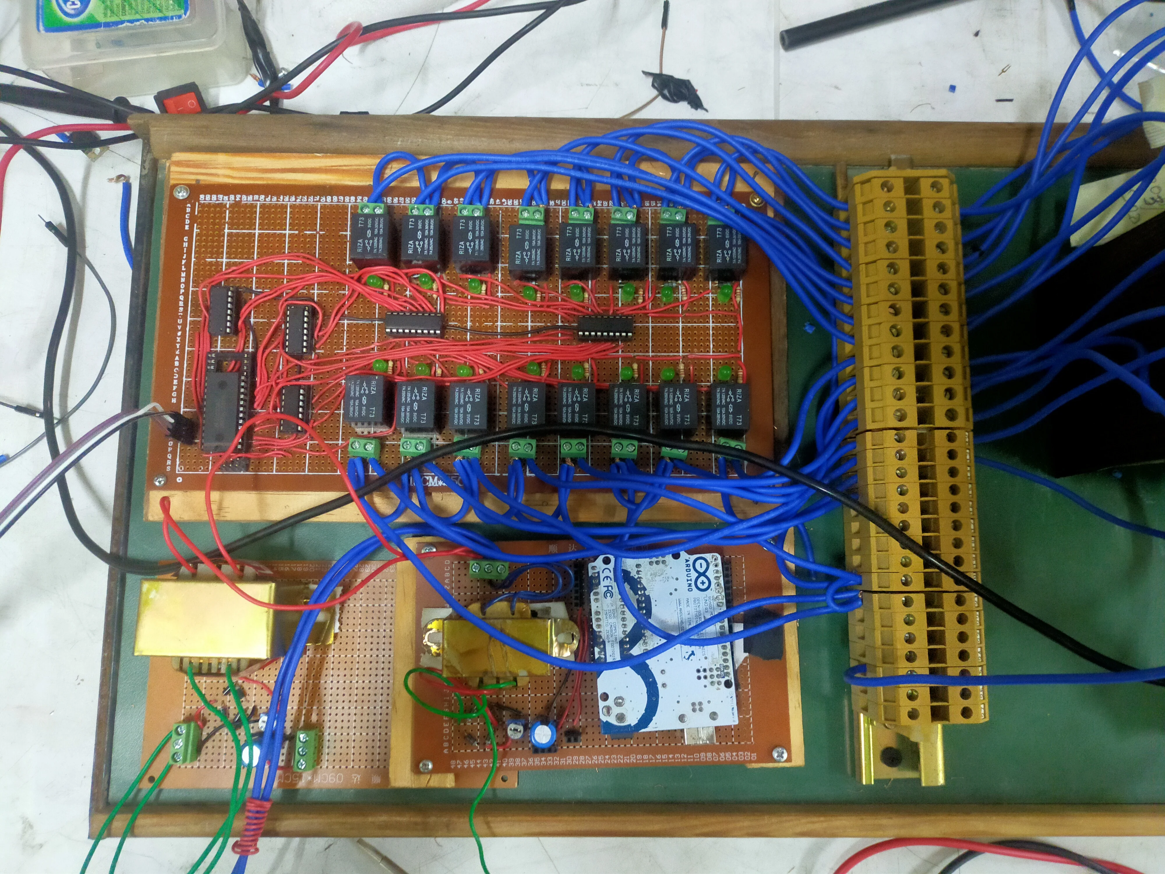
The PCB was fabricated and components were soldered in-house. Component placement separated the high-current relay and transformer section from the low-level sensing and logic section, with a ground-plane island under the analog comparator circuit to minimize noise coupling from relay coil transients. Snubber networks across each relay contact suppressed the inductive voltage spike generated when the transformer winding is interrupted during tap changes.
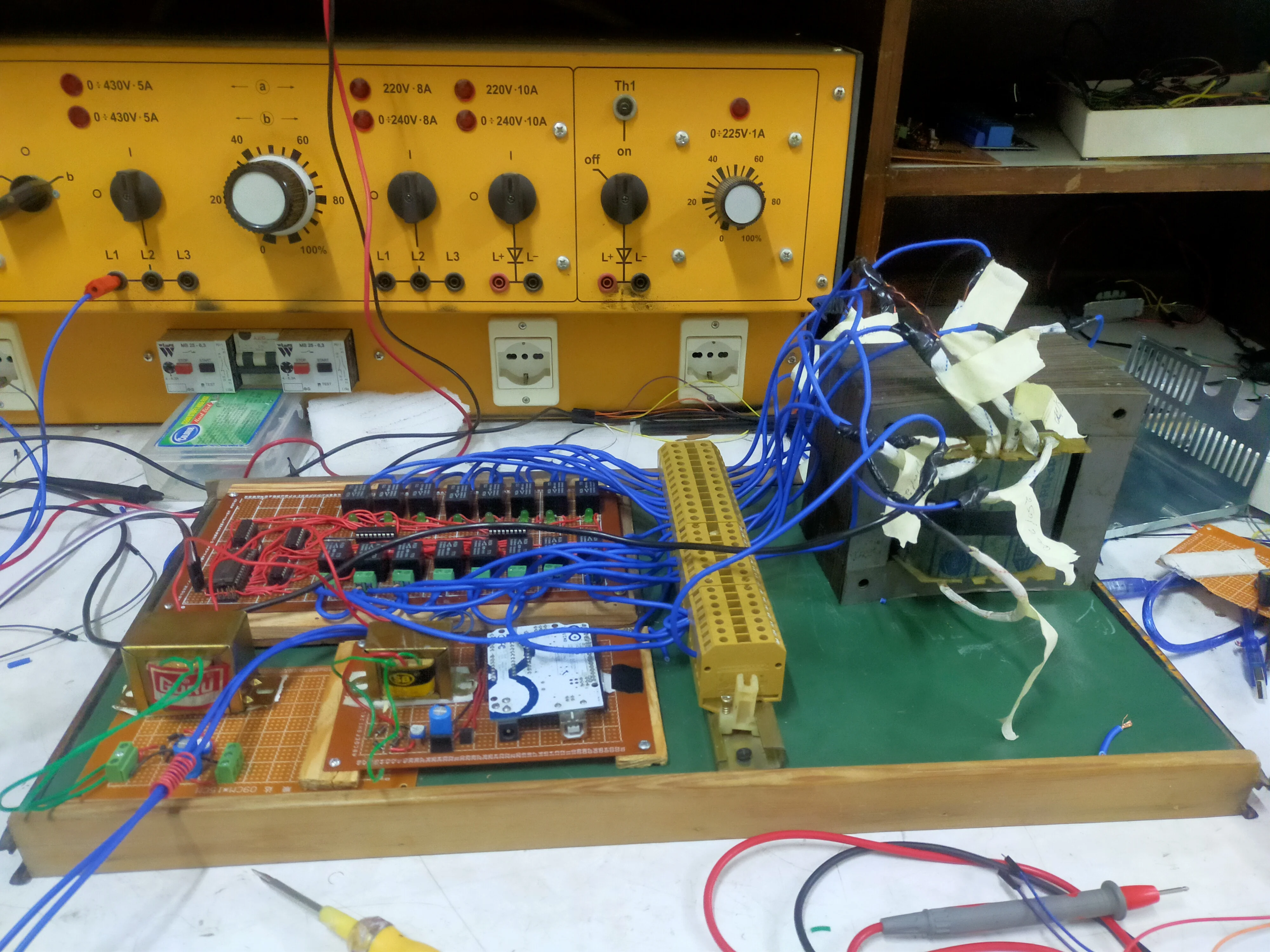
Project Gallery

Outcomes & Learnings
The stabilizer regulated output to 220 V ±5% across the full 160–260 V input range, covering the complete variability documented on Nepali distribution feeders. Tap switching settled to the correct position within two relay operations for all tested input conditions, and the output stabilized within one AC cycle of the final relay closure. No overshoot or hunting between adjacent taps was observed during steady-state testing at the input voltage boundaries.
The results were documented and published in the Journal of Physics: Conference Series (vol. 2629, no. 1, p. 012023, November 2023, doi:10.1088/1742-6596/2629/1/012023), providing a peer-reviewed record of the design parameters and measured performance. The project established hands-on competency in power electronics fabrication, relay control logic design, and voltage regulation circuit analysis — skills that directly informed subsequent work on power system protection and voltage stability at the graduate level.